The Sumo Bot was not fully completed. Three of my milestones were completed, I chose all of the necessary parts, I was able to get all the sensors working, and I was able to obtain DC and servo motor movement. Due to lack of time, I wasn’t fully able to construct the entire bot. The Arduino programs can be found below to get all the sensors working along with DC and servo motor movement. There is also a program that has motor movement based off the long range IR sensor data.
Moving forward, the next step should be redesigning the chassis. The SAC rules allow for a 10 cm width, the current chassis is just under 10 cm which is a draw back from the initial design. Previous students cut the chassis in the middle and took about 1.5 cm of each side and glued the chassis together. This will allow for the 3D printed body to cover up the wheels and add a pressure sensor (Velostat) on the sides. If not, only pressure sensors on the front and back can be added and would only control one servo with the pins. Therefore the chassis should be redesigned. Another suggestion Dr. Spalletta had was to 3D design and print the chassis and body as one which allows total customization to the user.
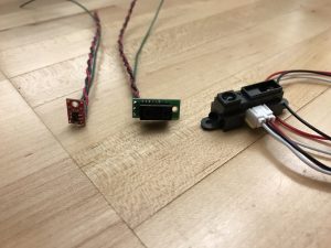
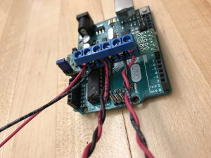
Once the chassis and body are determined and constructed, the sensors and servo motors should be mounted. The sensors are already wired by myself. An image can be found below, starting on the left, there is the line sensor, short range IR sensor, and the long range IR sensor. The power and GND lines should run to the voltage regulator circuit that was previously discussed in the week 6 of the notebook update along with a schematic. The green wire then should be attached to the desired pin on the Arduino. An image of the circuit can be found below. The red and black wires in the circuit attach to an 8 V battery.
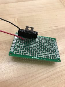
It is important to discuss the motor driver. Looking at the photo below there are 6 connections. Started on the left, the first two are reserved for power and GND (a 6 V battery should be attached here). The next two pins are motor 1 + and -. The last two pins are motor 2 + and -. In the picture there is a black wire connected to the positive pin, this is due to the way the motor is mounted. In order for both motor 1 and 2 to have the same logic during programming this change had to be made. If this change wasn’t made the forward direction for motor 1 is the backwards direction for motor 2. A sample program for movement can be found below. For forward direction movement the phase has to be LOW and for reverse movement it has to be HIGH.
Once fully constructed, an algorithm needs to be implemented. The logic I was going to implement was to start the bot by having the two motors run opposite directions until a target is spotted by the long range IR sensor. Once the target is spotted both motors would move in the forward direction. Once my bot is within a 10 cm range the short range IR sensor would take over to make adjustments to push the other bot. Two interrupts would be incorporated as well. If a line sensor was interrupted, the bot would turn around to get away from the edge of the ring depending on which sensor threw the interrupt. The other interrupt would be based on the pressure sensor (Velostat). If the velostat sensed a change, a pin driven by a servo would hit the ground at an angle that would limit the amount my bot would be able to be pushed and would push back in order to get off the pin. The next steps would then be to tweak the algorithm to make the reaction time shorter when sensing to have a dominant sumo bot.
Arduino Programs: